
Measuring motor vehicles and trailers
Inspection prior to registration is to:
- verify the vehicle's details match the vehicle details stated on the application
- assess the compliance of the vehicle dimensions.
Each vehicle that is inspected for registration must have a completed vehicle details inspection sheet (F3529) form with every inspection sheet.
This form contains information needed to register the vehicle that may not be on an inspection sheet. For example, the colour of the vehicle. Find out more about how to complete the vehicle details form.
If any identifiers are not located on the vehicle or trailer, the inspection must not proceed until all are located.
On this page:
- Trailers with low volume VIN
- Important points to remember when measuring
- Measuring height
- Measuring width
- Measuring length
- Dimensional limits
- Swept path
- Fifth wheel
- T measurement and king pin
- PH measurement
- Load sharing and non-load sharing axle systems
Trailers with low volume VIN
Trailers with a low volume VIN must attend a transport and motoring service centre with the identifier, so we can conduct an identity check prior to first registration. The purpose of this inspection is to confirm the identifier has been attached to the correct trailer and is stamped on the trailer and recorded on the identification plate. The identity check is only required the first time the trailer is registered with the identifier.
Not all of our transport and motoring service centres conduct identity checks. Please check the services provided by each centre to confirm if they can inspect the vehicle or trailer.
Important points to remember when measuring
Vehicles
When measuring a vehicle, make sure you measure to the widest point, excluding mirrors and/or clearance lights. However, if these lights have fixed steel or other material covering them, that should also be included in the measurement.
Caravans
When measuring a caravan, you must measure to the very rear and include spare tyre, bike racks, jerry can holders or ladders.
Trucks
When measuring trucks fitted with a tow coupling, you must include the tow coupling when measuring the length. You must also include any projections to the sides (for example, brackets for tying down the load or steps).
The standard measuring equipment required includes:
- telescoping height pole or laser measuring device
- plumb-bob
- steel measuring tape
- chalk.
Former Australian Defence Force (ADF) vehicles
Australian military vehicles are granted exemptions under the ADF Road Transport Exemption Framework, which permits their use on Australian roads specifically for defence purposes. These vehicles are often purpose-built or modified for military applications.
Due to their specialised military role, such vehicles may be exempt from certain Australian Design Rules (ADRs). As a result, they may not meet the requirements for registration in Queensland.
Before an ex-military vehicle can be registered in Queensland, it must comply with all relevant ADRs, including those relating to dimensions, lighting and vehicle security. It is important to note that an Identification Plate Approval (compliance plate) alone cannot be relied upon to assess the suitability of an ex-military vehicle for registration.
The Department of Transport and Main Roads has identified certain ex-military low-loader trailers exceeding the maximum vehicle dimensions, such as the Haulmark 4STL-55, which is 2.8 metres wide. These trailers do not meet Queensland's registration requirements and are ineligible for registration.
Measuring height
A height pole is extended, held vertically and placed adjacent to the highest point. The height measurement is taken from the gauged readout on the height pole.
Measuring width
Increased width for Safer Freight Vehicles
From October 2023, the Australian Government changed the national road vehicle standards to facilitate the supply of safer trucks in Australia, reduce road trauma and boost productivity.
The Safer Freight Vehicles package includes an increase to the overall width limit from 2.50 to 2.55 metres for new trucks fitted with a number of specific safety features.
The new safety features include devices to reduce blind spots, electronic stability control, advanced emergency braking, a lane departure warning system, more detailed reflective markings, and protection devices to help prevent vulnerable road users from being caught under the rear wheels of heavy vehicles.
Currently, the 2.55m is only available to new trucks with a Gross Vehicle Mass over 4.5t.
Single-measure method
When there is a projection from only 1 side of the vehicle, or where the widest point of projection on each side is at the same distance along the length of the vehicle, the following method can be used:
- Identify the widest point to be measured.
- Hold the plumb-bob against the widest point on 1 side. As far as practicable it should be parallel to the side of the vehicle. Mark that point on the ground.
- Similarly, mark the widest point on the other side of the vehicle. As far as practicable, the line between the 2 points should be perpendicular to the centreline of the vehicle.
- Measure the distance between the 2 points using a tape measure held taut along the ground.
Measurements are to be taken at the widest point excluding the following devices:
- Anti-skid devices mounted on wheels.
- Fitted central tyre inflation system.
- Fitted side marker light and fitted reflectors.
- Fitted mirrors/indirect vision system (camera).
- Fitted signalling devices.
- Fitted tyre pressure gauges.
- Permanently fixed webbing assembly-type device, including any part of the device load restraint. An example is a curtain side device.
- Removable load restraint equipment, if the overall width of the heavy vehicle, including any part of the equipment, is not more than 2.55m. At this stage, a Safer Freight Vehicle cannot exceed this allowance.
Vehicle-projection method
If the widest points on either side of a vehicle do not line up, the vehicle-projection method can be used:
- Starting on 1 side, identify the widest point.
- If the projection is flat and accessible, hold the tape against the edge of the projection and measure to the side of the vehicle. Mark this point on the ground. If the widest point is out of easy reach, hold a plumb-bob against the projection and mark this wide point on the ground.
- Holding the plumb-bob against the side of the vehicle, mark this point on the ground. Using a tape measure held taut along the ground, measure between the 2 points marked on the ground to find the width of the projection. Record this measurement.
- Repeat steps 1 to 3 for the other side of the vehicle if there are projections on both sides.
- Measure the width of the main vehicle by holding the plumb-bob against 1 side of the vehicle and mark this point on the ground. Repeat this step on the other side of the vehicle. Using a tape measure held taut along the ground, measure between these 2 points to find the main width of the vehicle. Record this measurement.
- Add the recorded measurements from steps 2 to 5 to get the total assessed vehicle width.
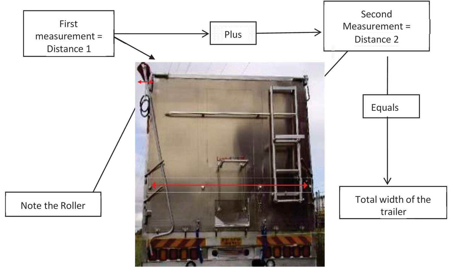
Caption—Measuring width
Measuring length
- Identify the extreme front point of the vehicle or trailer.
- Using a plumb-bob, mark this point on the ground and extend a straight line from that point past the side of the vehicle. As far as practicable, this line should be perpendicular to the centreline of the vehicle.
- Similarly, mark the extreme rear point and extend a line from there to the side of the vehicle.
- Measure the distance between the front and rear lines using a tape measure held taut along the ground.
- Alternatively, the vehicle can be moved (if possible) which will remove the need to extend lines past the side of the vehicle.
Measurements are to be taken at the longest point, excluding the following devices:
- fitted mirrors
- rubber bump stops fitted to the rear bumper bars of trucks and trailers.
Where possible, whenever assessing length, the measuring tape should run flat along the ground to avoid sagging or twisting which creates errors.
Dimensional limits
The correct assessment of vehicles and trailers is to ensure the safety of the towing vehicle, other road users and the road network assets.
Truck and trailer combinations must operate safely to reduce the risk that may arise from the demand road networks and traffic environment place on the manoeuvrability and stability of vehicles.
Improving vehicle stability assists in reducing incidences such as rollovers and loss-of-control crashes in heavy vehicles. It also reduces the tendency of heavy vehicles with trailers to jack-knife while undertaking emergency manoeuvres—in particular, when braking into corners.
Dimensional limits are set for vehicles and trailers to ensure minimum acceptable standards of road safety for all road users, as well as protecting the road system.
Internal dimensions (i.e. overhangs, location of turntables, axle spacing) are set to help vehicles safely navigate intersections and other road curves without encroaching on other traffic or roadside infrastructure.
External dimensions (i.e. length, width and height) are determined to help vehicles clear under/over bridges, power lines, fibre optic cables and roadside fixtures such as signs and guard rails. When width is considered, the following applies:
- Measurement is to be taken at the widest point excluding anti-skid devices mounted on wheels, central tyre inflation systems, lights, and mirrors, reflectors, signalling devices or tyre pressure gauges.
- It is also important that vehicles meet internal and external dimensional limits so that they don't exceed the swept path limits of roads where the swept path is the road area covered by the outermost and innermost points of the vehicle units during the turn.
Swept path
When a vehicle performs a turning manoeuvre, the rear of the vehicle or combination may cover a different path towards the inside of the turn than the path of the foremost vehicle unit.
When operating at maximum laden mass and unladen, the maximum width of the swept path of a vehicle in the prescribed 12.5m radius 90º turn, performed at a speed of no more than 5km/h, must be no greater than the specified value.
Find out more from the National Heavy Vehicle Regulator—see Section C7: Low-speed swept path of the Performance-Based Standards Scheme—Standards and vehicle assessment rules.
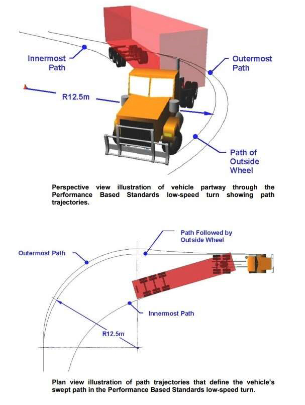
Caption—Illustrations showing swept path and path trajectories for a vehicle
Fifth wheel
Prime movers are fitted with a fifth wheel coupling. This provides a link between a semi-trailer and the towing vehicle, lead trailer or dolly through a connection between the turntable and a king pin.
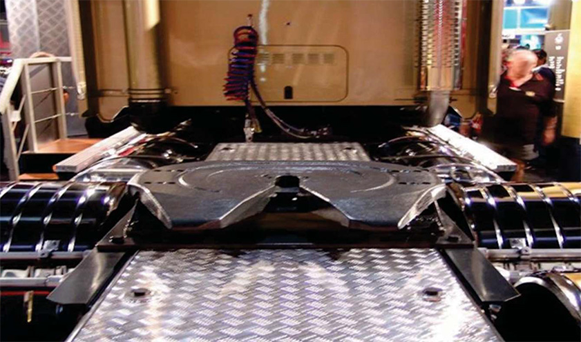
Caption—example of a fifth wheel coupling
T measurement and king pin
The 'T' measurement is the radial distance from the king pin. All trailer components forward of the king pin must be within 1.9m of the king pin. A king pin is a coupling pin welded or bolted in the centre of the front underside of a semi-trailer chassis, which couples to the fifth wheel of the prime mover or converter dolly.
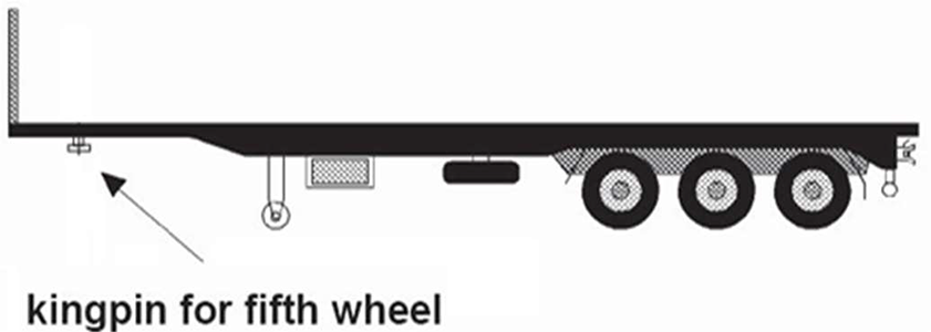
Caption—illustration showing location of kingpin for fifth wheel on a trailer
If the 'T' measurement cannot be taken this way, then Pythagoras theory can be used. This measurement indicates the swept path of the trailer when the prime mover negotiates a corner.
PH measurement
The PH measurement is the measurement from the headlights to the end of the projection point, in front of the headlights. The PH measurement is only applicable to loading on a vehicle not integral components such as booms.
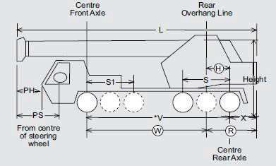
Caption—illustration of PH measurement for a vehicle
Load sharing and non-load sharing axle systems
There are 2 types of axle systems that are fitted to heavy vehicles and trailers:
It is very important that you correctly distinguish between the load sharing or non-load sharing axle systems. If the axle group is not fitted with an approved load sharing suspension (with effective damping characteristics) it is known as non-load sharing.
Effective damping characteristics are springs, coils or air bags suspension.
Load sharing suspension
Load sharing suspensions are designed so that each axle in a group carries the same load irrespective of the relative movement of the wheels.
Load-sharing suspension means an axle group suspension system is built:
- to divide the load between the tyres on the group so no tyre carries a mass more than 10% above the mass it would carry if the load were divided equally
- with effective damping characteristics on all axles of the group.
Not all load-sharing suspension is road friendly.
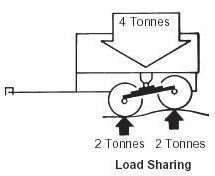
Caption—illustration showing example of a load-sharing suspension system on a trailer
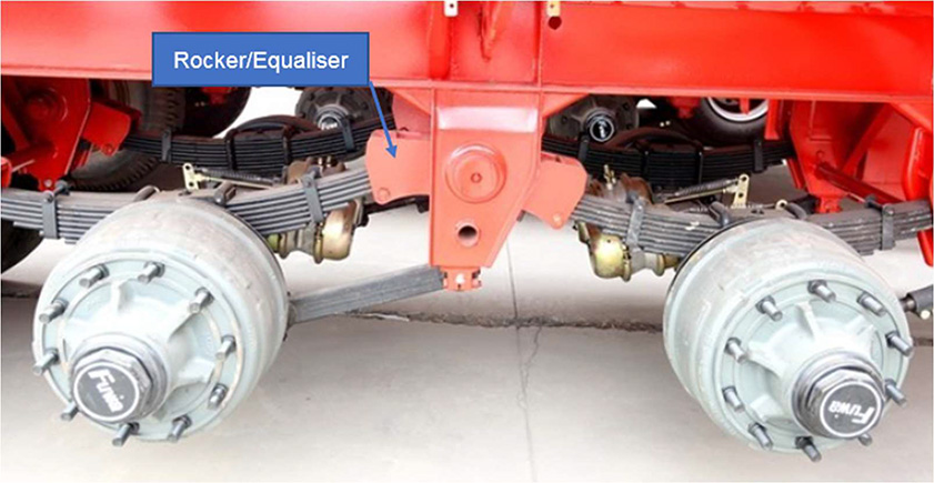
Caption—example of a rocker device
In this instance a device called a rocker is fitted between the axles, and the springs are attached to the rocker. If one axle moves over a rise in the pavement it causes the springs to push up on the rocker. The rocker acts like a see-saw forcing the other axle to remain in contact with the pavement.
Non-load sharing suspension
Each axle pack operates independently of the other axle.
The example below shows how a 4t load on a trailer with non-load sharing suspension distributes the load when going over an uneven surface on the road. The 4t load is only an indicator of a load on a trailer. When no device such as a rocker is installed the axles are unable to share the load when passing over an uneven surface.
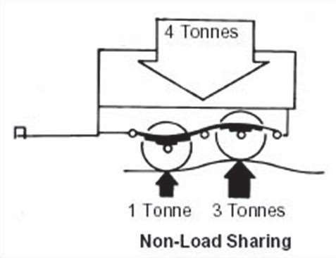
Caption—Example of a non-load sharing suspension system on a small trailer
More information
- Last updated
- 2 July 2026